Application note: Ethernet to SPI and Counter - Network Driven 7 Segment Indicators and Counters
 |
Preface
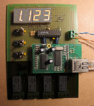
In this application note is shown how to count pulses, read them by a PC and show results on a seven segment indicators driven by MAX7219. All is done using an Ethernet connection between the PC and SR01E12 adapter. Two buttons are routed to the SR01E12 integrated counters, and corresponding pins are setup to digital inputs with pull up. Each button press increment related counter. A third button is connected to a GPIO pin, also setup to digital input with pull up. Its state is used for the PC software to decide which counter data to display on LED indication. SPI interface of SR01E12 controls the MAX7219 chip, which is connected to 4 seven segment LED indicators. MAX7219 is 5V chip and SR01E12 work on 3,3V, to match them a 5V tolerant pins are used on SR01E12 bridge. They are setup to open drain outputs and have external pull up resistors to 5V. On demo board exist 3,3V regulator for the Ethernet bridge and 5V regulator for the MAX7219 and LEDs.
Schematic
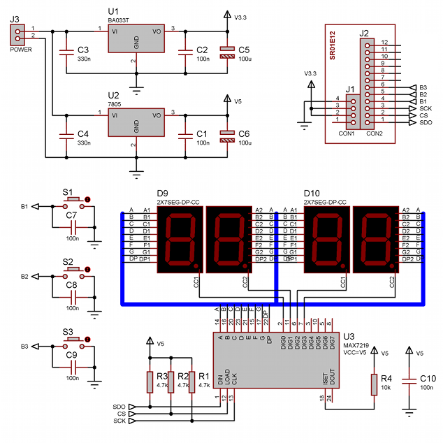
Board require 6,5-9V 400mA power supply to POWER connector. It can be provided by wall power adapter.
Software
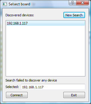
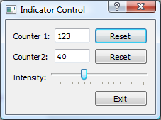
The user interface is built with QT framework. It is split in 2 dialogs, first is to obtain all network interfaces, search for SR01E12 boards and select one of them. A second dialog display counter values and has buttons to reset them.
Download
| CounterIndicator QT GUI Exec | QT GUI version - Executable file with all needed libraries |
| CounterIndicator QT GUI Src | QT GUI version - Source code (requires QT framework) |
Gallery
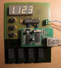 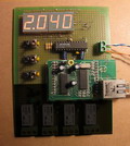 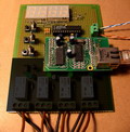 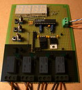 | Full Size |
* On grayed area of evaluation board are placed components not related to the project.
** Each button input has push button and toggle switch in parallel.

